
The Visual Study of Vacuum Tubes
Understanding how to perform the visual study of vacuum tubes can enable you to readily identify the unique characteristics and applications of a given tube. In The EICO 667 Vacuum Tube Tester I shared high-level information about what vacuum tubes are, their use cases, and how to test them. In the testing guide, I used a tube that is extremely common in guitar amplifiers, the 6V6GT. That said, vacuum tubes come in a wide variety of types and sizes that demand further exploration, each with a unique set of traits that ultimately determine their suitability for a particular application.
A breadth of resources discussing tube specifications, with an emphasis on theory and electrical engineering, however I have noticed a distinct lack of visual analyses available. I know I am not in the minority of folks who consider vacuum tubes visually pleasing pieces of artwork, each with their own unique characteristics. I intend to treat each analysis in this sense, with a calm and appreciative attention to visual detail and care one would apply to the admiration of art.
Before We Begin: A Note on Name Standardization
Vacuum tubes entered mass production in the early 20th century, a time when consistency in tube naming conventions was virtually nonexistent. In subsequent years, multiple standards emerged in an attempt to introduce some consistency to an otherwise unhelpful, dizzying array of tube names. For example, in 1965, the Radio Electronics Television Manufacturers’ Organization (RETMA) was formed and introduced an American tube naming convention. As is the case with most attempts at standardization, multiple other groups had their own standards, including Mazda, Mullard-Philips, European standards, and military standards.
It is important to recognize that depending on when and where a tube was manufactured, these rules don’t always apply and it’s always a good idea to check the spec sheet for your tube to verifying critical traits like filament voltage specs.
Rather than iterate through all of the different naming prefixes and suffixes (and characters between) that you may run into across all of the different standards, my intention is to make this the first in a series of posts where I will share a deeper dive per-tube analysis of some storied and visually striking vacuum tubes in my possession. I’ll be including photos, use cases, Eico 667 test parameters, and even questions I might have about the tubes I post. All of these tubes are for sale, and many are quite rare. If you’re interested in purchasing any, drop a note in the comments and we can discuss options.
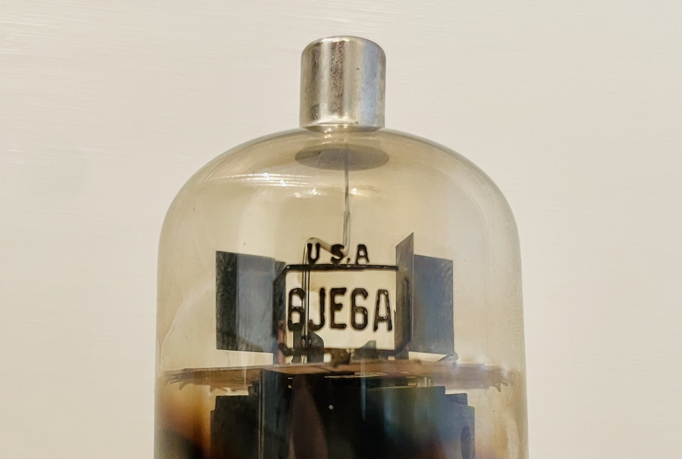
With that out of the way, let’s dive into our first analysis: an RCA 6JE6A.
RCA 6JE6A
Filament Voltage
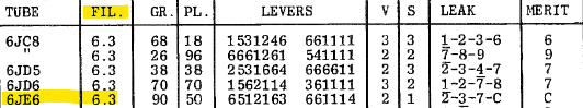
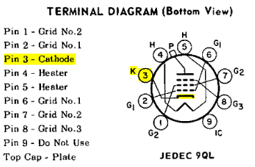
Simply by looking at the 6JE6A, we can glean some basic information about the technical characteristics of the tube: The prefix 6 indicates that it expects a filament voltage of 6.3V. Looking it up in the Eico 667 tube test chart is a way to validate this characteristic. Note that this chart shows 6JE6 (without the A suffix). The A (in this case) indicates a backward-compatible iteration on the original 6JE6 design:
The Circuitry
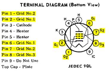
The 6JE6A has 9 exposed pins. 5 are grid pins, 1 is the cathode pin, two are heater pins, and one is structural.
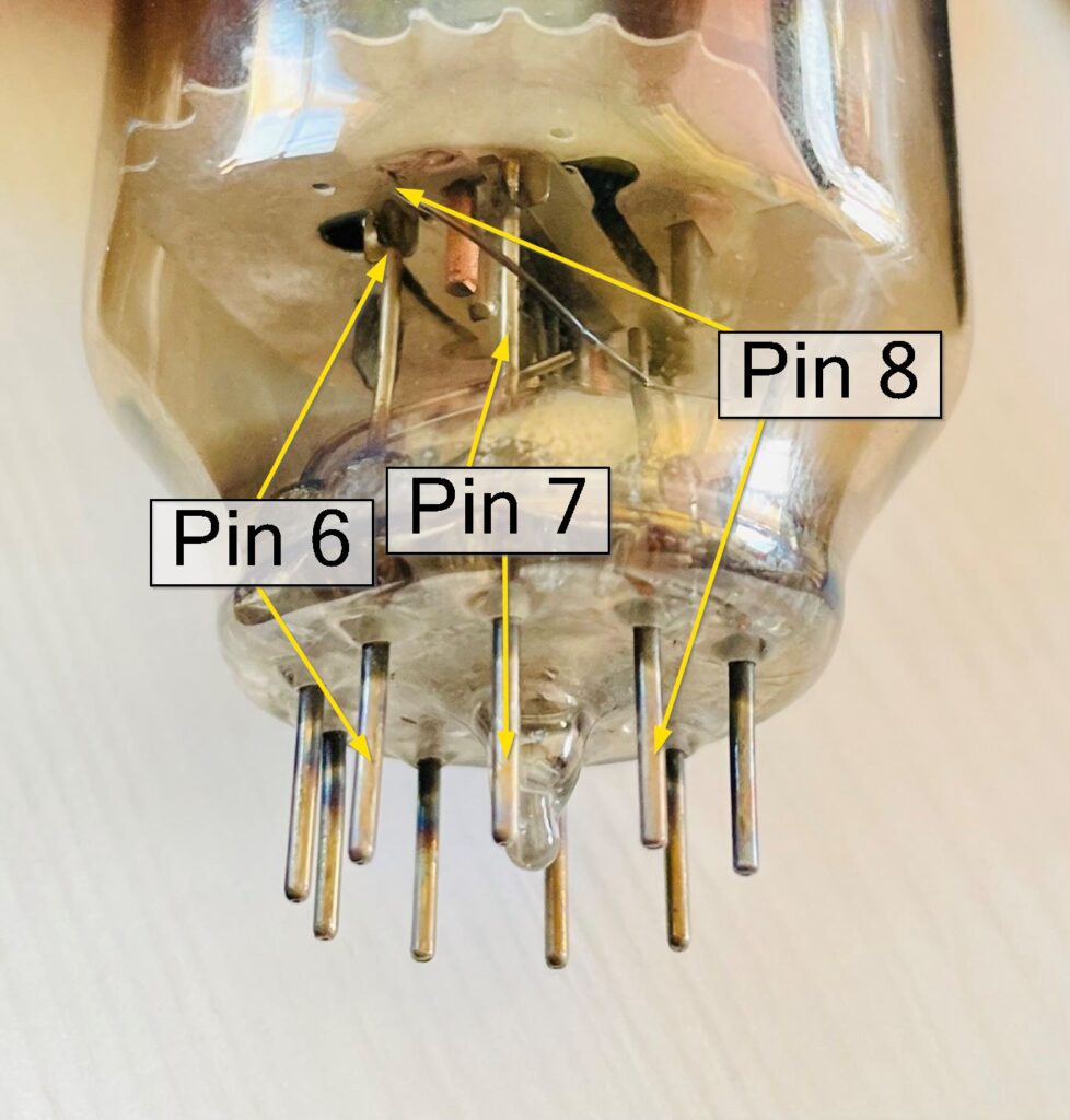
Grid Pins
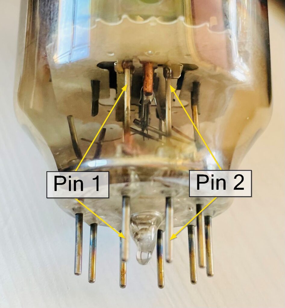
Pins 1, 2, 6, 7, and 8 all connect to the grid via grid lead wires. These can be visually traced to their contact points inside the tube, shown here. Note that Pin 8 is internally connected to the grid using a piece of lead wire soldered to the pin itself:
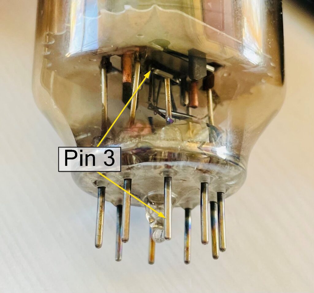
Cathode Pin
Pin 3 connects to the cathode, found centrally at the base of the inside of the tube. Note that like Pin 8, a lead wire inside the tube connects it to the cathode:
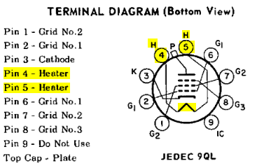
Heater Pins
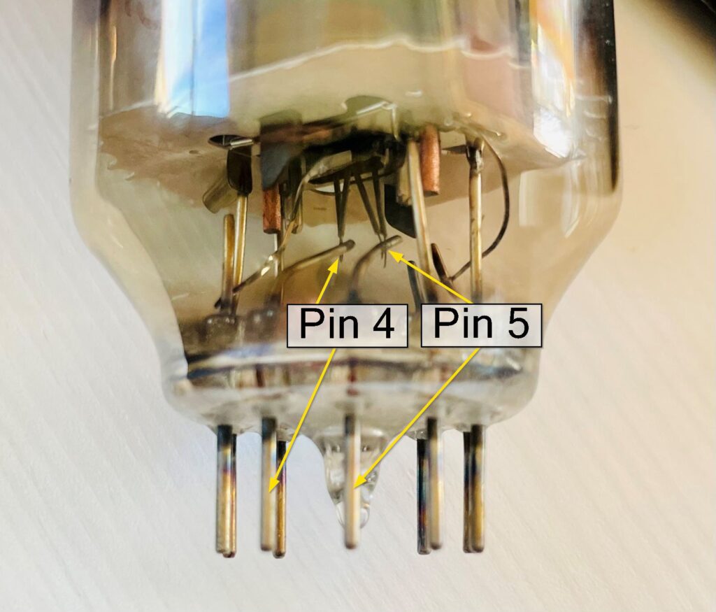
Pins 4 and 5 are bent upon entering the tube and soldered to the heater:
Structural Pins
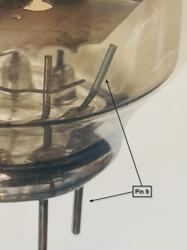
Not all of the pins in the 6EJ6A are actually connected to the internal circuitry of the tube. Pin 9 is marked as IC and Do Not Use on the terminal diagram provided by RCA, meaning that it’s simply there to provide structural support to the tube when it is inserted in a socket.
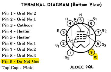
A visual inspection confirms this characteristic, where it’s plainly evident that Pin 9 doesn’t connect to anything inside the tube. Traits like these are a helpful way to confirm the identity of a tube if the name has worn off:
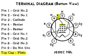
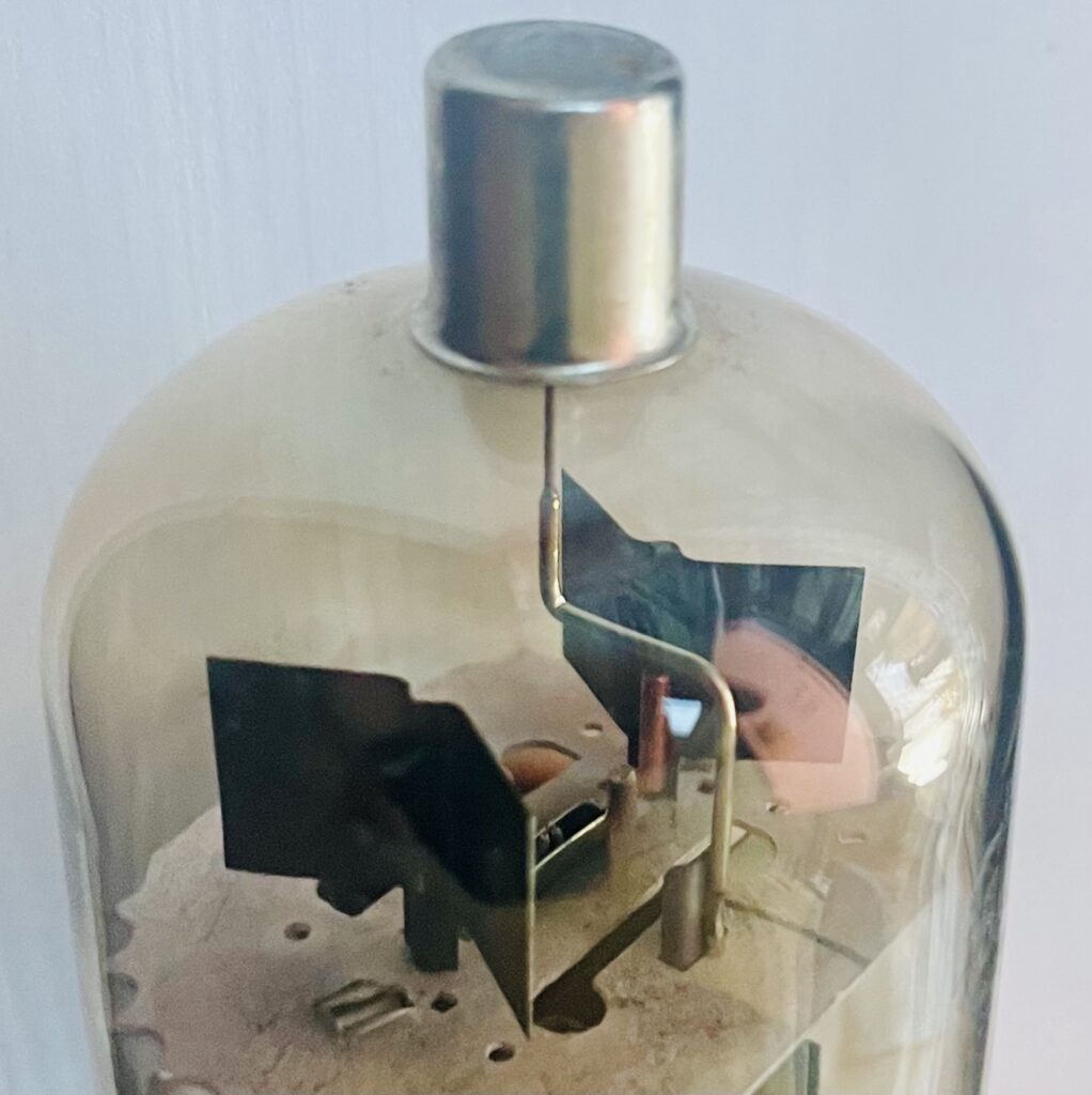
Top Cap
Not all tubes have top caps, but this one does. The top cap on this tube is connected to the plate via a lead wire at the top of the tube:
Use Cases
The RCA 6JE6A was introduced in the early 1960s and used in color television horizontal-deflection amplifier circuits. Horizontal deflection circuits move the electron beam to render an image from left to right in traditional CRT televisions. It is electronically equivalent to the 6LQ6 tube it superseded performance-wise, with an identical pinout and similar electrical characteristics.
Another use cases for the 6JE6A tube is in high-power linear amplifiers for amateur radio and CB radio applications such as the Dentron GLA-1000B.
It was widely available until the late 1970s, but production gradually declined as solid-state devices became more prevalent. Today, the tube is still available on the vintage electronics market, and it remains sought after among enthusiasts who appreciate its unique characteristics and historical significance.