Today we’re going to build a router. Yes, that’s right, we’re venturing into networking, which for many is uncharted, technically daunting territory. Together we will work through all of the steps required to build a high performance, Linux-based router I have named alpha — almost totally from scratch. What’s more, when it comes to speed, reliability, security, and customization, the router we build will exponentially beat just about any router you can buy at a big-box electronics store. In essence, this is one of those rare educational projects that also happens to provide tangible real-world utility in the form of a tiny beast of a home router that squashes any similarly-priced competition with ease. Let’s get started!
Disclaimer: Even though the mini-PC we use has an antenna, the router we’ll be building will have no built-in wireless functionality. Not only that, but even if I were to get the antenna working, much better performance can be had from a dedicated access point. As such, I’ve included an access point and Power-Over-Ethernet (PoE) gigabit switch in the hardware purchase list for this guide (and you can even purchase multiple access points to cover a larger house).
How Routing Works
Before we continue it’s important to have a high level understanding of how a traditional home router works. Just the basic facts.
Routers route traffic between two networks. Without them, the Internet as we know it simply wouldn’t exist. This is because the Internet is comprised of millions (maybe billions) of private networks all routed over multiple public networks.
Private network? Public Network? Wha…?
This might sound crazy, but let’s take a moment to build an analogy. I’ve found international travel standards to be a great way of explaining how routing works. Every country in the world has its own distinct security, rules, and culture, but how do we travel between different countries?
More often than not, we hop onto an airplane or a train with a lot of other people. These vehicles traverse the space between point A and point B, and ultimately we end up at our destination country. Once we’ve arrived, we typically have to go through some security checkpoint, and once we’ve cleared that, we’re finally inside our destination country. Private networks are like countries. We’re like packets (discrete chunks) of data sent over the Internet. Airports and train stations are like routers. The space between countries where we travel with many others is like the public Internet. A security checkpoint at the entryway to a country is like a firewall that sits in front of a private network allowing/denying access.
| Travel Metaphor | Technical Equivalent |
|---|---|
| Countries | Private Networks |
| Humans | Packets (Data) |
| Airports/Train Stations | Routers |
| Crowded Airplanes/Trains | Public Data Cables |
| Paths Between Sources/Destinations | Public Networks |
| Security Checkpoints | Firewalls |
In more concrete terms, your private network is like your country. It’s the network in your home to which your laptop, your fancy new smart TV, and maybe even your thermostat are connected. Just about any device in your home that you connect to wifi (not cellular, this is different!) or plug an Ethernet cable into is on your private network, and they can all talk to each other too (believe it or not, without needing a router). This is all great but without a way to get out of our private network there isn’t an Internet to browse! A router facilitates this transmission of data in and out of a private network.
You’ll often hear private networks described as local area networks, or LANs for short. I’ll be using the term LAN from here on out in this guide. Also, the term WAN (short for wide area network) is used to describe public networks, or the public Internet connection that connects to your router.
Hardware
With this new knowledge, we can safely assume that for a home router to work it needs at least two network interfaces. We’ll plug the public WAN (public network) connection into the first of these interfaces, and we will plug our private LAN connection into the second of the two interfaces.
Note: There are virtually infinite options here — you can scrounge up an old PC and install two gigabit network cards in it, or you can purchase something much smaller that also meets these requirements.
Here is all of the exact hardware I used to write this guide. If you purchase the following hardware and follow this guide exactly, you’ll have an exact clone of my router:
| Hardware Type | Link to Purchase |
|---|---|
| Mini PC | ZOTAC ZBOX C Series Passive Cooling Mini PC, Intel N3150 Quad-Core CPU, Intel HD Graphics Barebones System (ZBOX-CI323NANO-U) |
| Memory (RAM) | Crucial 8GB Kit (4GBx2) DDR3L 1600 MT/s (PC3L-12800) SODIMM 204-Pin Memory – CT2KIT51264BF160B |
| Hard Drive | Samsung 850 EVO – 250GB – 2.5-Inch SATA III Internal SSD (MZ-75E250B/AM) |
| Gigabit Switch with Power Over Ethernet (for connecting the wireless access point) | NETGEAR 8-Port Gigabit Ethernet Switch with 4-Port PoE (GS308P-100NAS) |
| Wireless Access Point | Ubiquiti Networks Unifi 802.11ac Dual-Radio PRO Access Point (UAP-AC-PRO-US) |
Installing the RAM and hard drive in the Mini PC is very straightforward (the only tool required is a Phillips head screwdriver used on a total of 4 screws), and the Mini PC comes with very good picture-guide and manual explaining how to accomplish this.
Software
We’re going to use Ubuntu Xenial Xerus Server 16.04.1 LTS 64-bit for our base operating system. Download the .iso file from the provided link. It will need to be put onto a USB stick for installation on the Mini PC, as the Mini PC doesn’t have an optical drive. We won’t cover this step here, as very good guides on how to do this are already available for Windows, Ubuntu Linux, and OS X.
BIOS Configuration
The BIOS on the Mini PC has a few settings that together prevent USB sticks from booting. To fix this, we need to plug a keyboard and monitor into the Mini PC and power it on. The Mini PC should then immediately load the BIOS Setup Utility. These setting changes will allow us to boot from a USB drive:
- Under the Security tab, change Secure Boot to Disabled.
- Under the Boot tab, change Boot Mode to Legacy Only.
- Under the Save&Exit tab, choose Save Changes and Exit.
Installing the OS
Once the BIOS settings are changed, we’re ready to install Ubuntu. This will be a very generic Ubuntu Server install (not too much custom about it beyond selecting a hostname, which can be anything you’d like. I named my router “alpha”).
Network Configuration
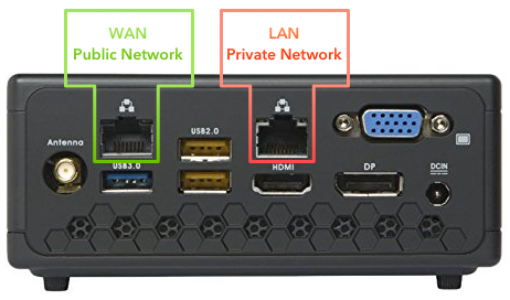
At a certain point in the operating system installation Ubuntu will attempt to automatically configure a network connection using DHCP. This allows your existing DHCP server, which typically runs on most commercial/ISP provided home routers, to assign a private IP address to the WAN interface on this router. My ISP (Verizon) uses the same method to assign an IP address from their public IP ranges to any WAN interface, so this is actually a great way to identify the physical (as in real-world) interface we want to use for our WAN connection. On the Mini PC I am using for this guide (available for purchase here), we’ll be configuring the interfaces as shown in Figure 1. Note: There’s no reason these interfaces couldn’t be swapped in how they’re used — in fact, that’s part of the beauty of a custom build — but for the sake of consistency I went with this arrangement of WAN on the left, LAN on the right.
To ensure DHCP assigns an IP to the correct (WAN) interface, we can use quick trial and error. All we need to do is connect a network cable from our existing soon-to-be-deprecated-big-box-or-ISP-provided router to the WAN interface on our new Mini PC router. It’s very important that there’s no connection from our existing router to the LAN interface (leave the LAN interface totally unplugged for now). Then we tell the Ubuntu installer to attempt to get an IP address using DHCP. If it succeeds, we’re ready to move on. If it doesn’t succeed, it just means we need to try the other of the two interfaces presented in the on-screen installation dialog, as this is the only one left that could possibly be the WAN interface labeled in green in Figure 1. Once it succeeds in getting an IP, proceed. Additionally, when this step is finished, it’s wise to stick a label on each of the two physical interfaces indicating their purpose (WAN and LAN).
Once the Ubuntu OS installation finishes, it’s time to get into the nitty gritty of what I call “post-installation” configuration. We are going to:
- Configure the LAN interface with a static IP (which will become our gateway IP for all connected clients on the network).
- Configure routing between the WAN and LAN interfaces.
- Configure an IPTables-based firewall with port forwarding functionality.
- Install and configure a DHCP server (so clients on our LAN can automatically get valid IP addresses as soon as they’re plugged into the network)
- Configure NAT
- Configure DNS to wrap things up.
This sounds like a lot of work, but we’ll go through each step together, and in the end it’ll be very much worth all the effort. Once we’re done this little Mini PC will absolutely delight as a tiny beast of a quad-core router that is easy to administer over SSH from our private network.
Post-Installation Configuration
LAN Interface Configuration and Packet Forwarding
Using a text editor (for the comfortable Linux user, vim or emacs, for the less-comfortable, nano), open /etc/network/interfaces. The file looks like this by default:
# This file describes the network interfaces available on your system
# and how to activate them. For more information, see interfaces(5).

source /etc/network/interfaces.d/*

# The loopback network interface
auto lo
iface lo inet loopback

# The primary network interface
auto enp3s0
iface enp3s0 inet dhcp
Let’s take a moment to review what we’re looking at here. The most relevant section in the default configuration is the primary network interface section. This is where our WAN interface (the one we set up during the OS installation) is configured. Notice that it’s configured for DHCP. This is exactly what we want. When we plug this interface into a network (whether public or private) that supports DHCP, we want it to be assigned an IP address on this network. Right now it’s on our existing private home network (so yes, technically it’s currently a LAN interface). Ultimately this interface will be connected to our public network cable and assigned an IP address from our ISP, and it will truly become the WAN interface it’s destined to be.
There’s something glaring missing here though — there’s no LAN interface! Exit this file and run ip addr at the CLI. This will generate a list of available network interfaces. Here we can see enp2s0 (unconfigured) and enp3s0 (configured as the WAN interface already via DHCP during the OS install phase earlier):
smalleycreative@alpha:~$ ip addr
1: lo: <LOOPBACK,UP,LOWER_UP> mtu 65536 qdisc noqueue state UNKNOWN group default qlen 1
    link/loopback 00:00:00:00:00:00 brd 00:00:00:00:00:00
    inet 127.0.0.1/8 scope host lo
       valid_lft forever preferred_lft forever
    inet6 ::1/128 scope host
       valid_lft forever preferred_lft forever
2: enp2s0: <BROADCAST,MULTICAST> mtu 1500 qdisc pfifo_fast state DOWN group default qlen 1000
    link/ether 00:01:2e:6e:67:60 brd ff:ff:ff:ff:ff:ff
3: enp3s0: <BROADCAST,MULTICAST,UP,LOWER_UP> mtu 1500 qdisc pfifo_fast state UP group default qlen 1000
    link/ether 00:01:2e:6e:67:61 brd ff:ff:ff:ff:ff:ff
    inet 192.168.2.87/24 brd 192.168.2.255 scope global enp3s0
       valid_lft forever preferred_lft forever
    inet6 fe80::201:2eff:fe6e:6761/64 scope link
       valid_lft forever preferred_lft forever
4: wlp4s0: <BROADCAST,MULTICAST> mtu 1500 qdisc noop state DOWN group default qlen 1000
    link/ether 2c:6e:85:7c:6e:ab brd ff:ff:ff:ff:ff:ff
Thanks to this output we now know the name of the LAN interface, and we can use that in our /etc/network/interfaces file to configure it with what is called a static IP address.
Technical note: For the purposes of this guide I decided on a single, huge class-A private subnet of
10.0.0.0/8for my home network, but you’re free to use any others if you’re comfortable doing so. Just be sure it doesn’t conflict with the subnet on the WAN side during configuration or strange behavior could occur. For example, if your existing home network is192.168.0.0/24, don’t configure your new range to be192.168.0.0/24or you won’t be able to properly test routing prior to putting this router into production by replacing your old one and plugging in the actual WAN connection.
Edit the /etc/network/interfaces file to look like this:
# This file describes the network interfaces available on your system
# and how to activate them. For more information, see interfaces(5).
source /etc/network/interfaces.d/*

# The loopback network interface
auto lo
iface lo inet loopback

# The WAN network interface
auto enp3s0
iface enp3s0 inet dhcp

# The LAN network interface
auto enp2s0
iface enp2s0 inet static
address 10.0.0.1
network 10.0.0.0
netmask 255.0.0.0
broadcast 10.255.255.255
Now if we run sudo systemctl restart networking.service, and then run ip addr at the CLI, we should see enp2s0 (the LAN interface) is configured with an IP:
smalleycreative@alpha:~$ ip addr
1: lo: <LOOPBACK,UP,LOWER_UP> mtu 65536 qdisc noqueue state UNKNOWN group default qlen 1
    link/loopback 00:00:00:00:00:00 brd 00:00:00:00:00:00
    inet 127.0.0.1/8 scope host lo
       valid_lft forever preferred_lft forever
    inet6 ::1/128 scope host
       valid_lft forever preferred_lft forever
2: enp2s0: <NO-CARRIER,BROADCAST,MULTICAST,UP> mtu 1500 qdisc pfifo_fast state DOWN group default qlen 1000
    link/ether 00:01:2e:6e:67:60 brd ff:ff:ff:ff:ff:ff
    inet 10.0.0.1/8 brd 10.255.255.255 scope global enp2s0
       valid_lft forever preferred_lft forever
3: enp3s0: <BROADCAST,MULTICAST,UP,LOWER_UP> mtu 1500 qdisc pfifo_fast state UP group default qlen 1000
    link/ether 00:01:2e:6e:67:61 brd ff:ff:ff:ff:ff:ff
    inet 192.168.2.87/24 brd 192.168.2.255 scope global enp3s0
       valid_lft forever preferred_lft forever
    inet6 fe80::201:2eff:fe6e:6761/64 scope link
       valid_lft forever preferred_lft forever
4: wlp4s0: <BROADCAST,MULTICAST> mtu 1500 qdisc noop state DOWN group default qlen 1000
    link/ether 2c:6e:85:7c:6e:ab brd ff:ff:ff:ff:ff:ff
This is a big step! We have two network interfaces up and running now! As it stands, Linux itself will not allow network traffic to be forwarded between these two networks, so the next step is to enable packet forwarding for all network interfaces. This is very simply accomplished by editing /etc/sysctl.conf and uncommenting the line that says net.ipv4.ip_forward=1 by deleting the # sign before it. Save this change and then run sudo sysctl -p from the CLI to refresh the configuration, allowing packet forwarding.
IPTables
iptables has been the most widely used Linux firewall for many years, and we’re going to use it quite a bit on our router for forwarding traffic to and from our WAN and LAN networks. For more information on what it can do, check out the official Ubuntu IPTables documentation, which was a huge help when I was configuring my router for the first time. The first task we’ll accomplish using IPTables will be to configure rules for packet forwarding that are applied before the network interfaces come up so that when our router boots or reboots, traffic is immediately forwarded as expected. To achieve this, first, install iptables-persistent, which allows iptables rules to persist between reboots.
sudo apt install -y iptables-persistent netfilter-persistent
Then run the following commands (you can paste this into your terminal after running the first sudo command):
# Create a file at /etc/network/if-pre-up.d/iptables
sudo touch /etc/network/if-pre-up.d/iptables
# Copy the required pre-up iptables commands into /etc/network/if-pre-up.d/iptables
sudo bash -c "cat >/etc/network/if-pre-up.d/iptables <<EOL
#!/bin/sh
/sbin/iptables-restore < /etc/iptables/rules.v4
EOL"
sudo chown root:root /etc/network/if-pre-up.d/iptables
sudo chmod 755 /etc/network/if-pre-up.d/iptables
In essence, what we’ve just done is told Linux that we want to restore our IPTables configuration prior to bringing up any network interfaces during system startup. This ensures we’re never caught without a firewall configuration during router booting or reboots of the router — because power outages happen!
If we run sudo iptables -L right now, the output looks like this:
smalleycreative@alpha:~$ sudo iptables -L
Chain INPUT (policy ACCEPT)
target     prot opt source               destination

Chain FORWARD (policy ACCEPT)
target     prot opt source               destination

Chain OUTPUT (policy ACCEPT)
target     prot opt source               destination
Pretty sparse, huh? We’re going to flesh this out with NAT rules next. This is what allows traffic to leave our LAN (private network) and head out to the WAN (public network) while “masquerading” behind a single public IP. If you want to learn more about NAT, read on.
How NAT (Network Address Translation) Works
Analogy time again! To understand Network Address Translation, it helps (once again) to look at a real-world analog: the U.S. Postal Service. If there has ever been a time when you’ve needed to send postal mail to a person at an organization such as a fictional paper company in Scranton, PA, you’ve probably done something like this:
ATTN Michael Scott
Care of Dunder Mifflin Paper Company
1725 Slough Avenue, Scranton, PA
Inevitably, if the USPS is working as it should, your mail delivery will arrive at the desk of Dunder Mifflin’s Scranton’s receptionist, Pam. She then takes this mail and hands it off to Michael Scott.
The address and business name are the equivalent of a public IP address on a WAN interface. The ATTN line above this is the equivalent of a NAT mapping. Any time a packet leaves a private home network (which presumably has multiple devices inside it), the router makes a note of the device that sent the traffic before routing it out to the internet and replacing the source IP with the public WAN IP of the router. This way the recipient somewhere out there on the Internet knows the origin public IP address of the router that sent them the packet. Internet traffic typically demands a response — when we go to www.google.com we expect the page to load on our machine, which means there is return traffic from Google to us. Our router remembers the IP on our network that made the original request, takes this return traffic, and routes it to the correct internal private IP address that requested it.
Now that NAT has been explained, it’s time to configure it!
NAT Configuration
It’s time to get back to configuring our router. To configure NAT, we edit the /etc/iptables/rules.v4 file and add the following content (after the first commit we have the remainder of the IPTables configuration for ease of use — we can just copy this into our /etc/iptables/rules.v4 file and the IPTables configuration is done). Anything that isn’t explicitly allowed here is denied, which makes for a very secure router:
###########
### NAT ###
###########
*nat
:PREROUTING ACCEPT [0:0]
:INPUT ACCEPT [0:0]
:OUTPUT ACCEPT [0:0]
:POSTROUTING ACCEPT [0:0]

# Enable NAT on WAN interface enp3s0
-A POSTROUTING -o enp3s0 -j MASQUERADE


#### Port Forwarding Section 1 - Add any port forwarding rules here and in Section 2 ####
# Example: Port forward HTTP traffic from WAN to LAN client 10.0.0.2
-A PREROUTING -p tcp -m tcp -i enp3s0 --dport 80 -j DNAT --to-destination 10.0.0.2:80


COMMIT

*filter
:INPUT ACCEPT [0:0]
:FORWARD ACCEPT [0:0]
:OUTPUT ACCEPT [0:0]

################
### Services ###
################

# ICMP/Loopback - Accept all traffic from the router to itself (loopback) and ICMP (e.g. ping) traffic
-A INPUT -s 127.0.0.0/8 -d 127.0.0.0/8 -i lo -j ACCEPT
-A INPUT -p icmp -j ACCEPT
-A INPUT -m state --state ESTABLISHED -j ACCEPT

# Traceroute - Send a traceroute reject message instead of doing nothing when a client traceroute hits the router
-A INPUT -p udp -m udp --dport 33434:33523 -j REJECT --reject-with icmp-port-unreachable

# DNS - Accept DNS requests traffic (port 53) from the private LAN interface
-A INPUT -i enp2s0 -p tcp --dport 53 -j ACCEPT
-A INPUT -i enp2s0 -p udp --dport 53 -j ACCEPT

# SSH - Accept SSH traffic (port 22) from the private LAN so we can manage the router from any machine on the private network
-A INPUT -i enp2s0 -p tcp --dport 22 -j ACCEPT

# DHCP - Accept DHCP requests from the private LAN so that clients can get IP addresses from the router
-A INPUT -i enp2s0 -p udp --dport 67:68 -j ACCEPT

# Drop any other traffic that hits the router
-A INPUT -j DROP

########################
### Forwarding rules ###
########################

# forward packets to related/established connections
-A FORWARD -m conntrack --ctstate RELATED,ESTABLISHED -j ACCEPT

# Forward from LAN enp2s0 interface to WAN enp3s0 interface
-A FORWARD -i enp2s0 -o enp3s0 -j ACCEPT


#### Port Forwarding Section 2 - Add any port forwarding rules here and in Section 1 ####
# Example: Allow HTTP traffic from our NAT rule to client 10.0.0.2
-A FORWARD -p tcp -d 10.0.0.2 --dport 80 -j ACCEPT


# drop all other forwarded traffic
-A FORWARD -j DROP

COMMIT
We can save this file, but we’re going to hold off on restarting IPTables for the time being. First, we’ll want to configure DHCP and DNS.
DHCP Server
Running a DHCP server on our router allows our router to hand out address to clients that are connected to it on the LAN interface (e.g. laptops/iPads/thermostats). Before this will work we need to install the DHCP server and configure it. This step (and DNS) are pretty straightforward.
To install the DHCP server, simply run:
sudo apt install -y isc-dhcp-server
The next step is to configure DHCP so that it hands out IP addresses on the network we want to use. In this example, I purposely omit potential client IPs of 10.0.255.255 through 10.255.255.254 and set my range (the set of IPs I want my router to automatically hand out to internal clients) to a max of 10.0.255.254. I do this for two reasons:
- It’s nice to have a range of IPs that we can use for static addressing on clients without worrying that DHCP is going to conflict with them (IP conflicts are a fundamental sin of networking and will cause all sorts of problems). This way we can manually configure a client with any valid IP above
10.0.255.254and it will work without conflicting with the DHCP range. - If I were to tell the DHCP server to use every available IP in
10.0.0.0/8, DHCP would fail to start on the router because there are built-in failsafes in place that prevent DHCP from using up all of the available system memory, as this large of a range would.
We put our desired DHCP configuration in place by adding the following stanza to the end of /etc/dhcp/dhcpd.conf. Be sure to change the domain-name to something you like for your own network, but keep the .local at the end:
subnet 10.0.0.0 netmask 255.0.0.0 {
  range 10.0.0.2 10.0.255.254;
  option routers 10.0.0.1;
  option domain-name-servers 10.0.0.1;
  option domain-name "smalleycreative.local";
  option broadcast-address 10.255.255.255;
}
To finish up with DHCP, restart the ISC DHCP service by running:
sudo systemctl restart isc-dhcp-server
Finally, we’re ready to tackle what may surprise you as the penultimate and easiest step — DNS!
DNS Server
Running a DNS server on our router allows our router to resolve hostnames for clients that are connected to it on our private LAN interface (e.g. laptops/iPads/thermostats). Before this will work we need to install the DNS server.
To install the DNS server, run:
sudo apt install -y bind9
There is some post-configuration required for DNS. Open /etc/bind/named.conf.options and make sure it looks like this:
options {
        directory "/var/cache/bind";

        // If there is a firewall between you and nameservers you want
        // to talk to, you may need to fix the firewall to allow multiple
        // ports to talk.  See http://www.kb.cert.org/vuls/id/800113

        // If your ISP provided one or more IP addresses for stable
        // nameservers, you probably want to use them as forwarders.
        // Uncomment the following block, and insert the addresses replacing
        // the all-0's placeholder.

         forwarders {
                8.8.8.8;
                8.8.4.4;
         };

         allow-query {
                10.0.0.0/8;
                127.0.0.1;
         };

         allow-transfer {
                10.0.0.0/8;
                127.0.0.1;
         };
        //========================================================================
        // If BIND logs error messages about the root key being expired,
        // you will need to update your keys.  See https://www.isc.org/bind-keys
        //========================================================================
        dnssec-validation auto;

        auth-nxdomain no;    # conform to RFC1035
        listen-on-v6 { any; };
};
We’re specifically concerned with the forwarders, allow-query, and allow-transfer sections. They should look exactly as shown above (if you’re compelled to, you can substitute out 8.8.8.8 and 8.8.4.4 for your public DNS servers of choice — I like using Google DNS at these two 8.8.x.x IPs).
To finish the DNS configuration, restart the DNS service:
sudo systemctl restart bind9
Restart IPTables
To wrap up our router build, we can restart iptables by running:
sudo systemctl restart netfilter-persistent
Finally, verify the configured rules are in place by running iptables -L -n -t nat. For example:
smalleycreative@alpha:~$ sudo iptables -L -n -t nat
Chain INPUT (policy ACCEPT)
target     prot opt source               destination
ACCEPT     all  --  127.0.0.0/8          127.0.0.0/8
ACCEPT     icmp --  0.0.0.0/0            0.0.0.0/0
ACCEPT     all  --  0.0.0.0/0            0.0.0.0/0            state ESTABLISHED
REJECT     udp  --  0.0.0.0/0            0.0.0.0/0            udp dpts:33434:33523 reject-with icmp-port-unreachable
ACCEPT     tcp  --  0.0.0.0/0            0.0.0.0/0            tcp dpt:53
ACCEPT     udp  --  0.0.0.0/0            0.0.0.0/0            udp dpt:53
ACCEPT     tcp  --  0.0.0.0/0            0.0.0.0/0            tcp dpt:22
ACCEPT     udp  --  0.0.0.0/0            0.0.0.0/0            udp dpts:67:68
DROP       all  --  0.0.0.0/0            0.0.0.0/0

Chain FORWARD (policy ACCEPT)
target     prot opt source               destination
ACCEPT     all  --  0.0.0.0/0            0.0.0.0/0            ctstate RELATED,ESTABLISHED
ACCEPT     all  --  0.0.0.0/0            0.0.0.0/0
ACCEPT     tcp  --  0.0.0.0/0            10.0.0.2             tcp dpt:80
DROP       all  --  0.0.0.0/0            0.0.0.0/0

Chain OUTPUT (policy ACCEPT)
target     prot opt source               destination
The End?
At this point it is time to test our work by plugging in a real WAN connection on the WAN interface of the router, and a laptop or any other device capable of receiving a network address via DHCP on the LAN interface of the router. It should “just work”.
There’s just one relatively major issue — how do we connect multiple clients on the LAN interface? It’s time to bust out our trusty PoE gigabit switch from the hardware list above! Simply plug this into the LAN interface, and then connect your clients to that. For wifi support, plug the Unifi Access Point from the hardware list above into one of the powered interfaces on the PoE switch and follow the Ubiquiti installation guide.
Colophon
This was a really fun project that I encourage you to try yourself. You’ll gain a better understand of how networks work, better performance for your home network, and the ability tweak and customize it to your hearts content. I hope you enjoyed the journey!
As always, if you have any questions do not hesitate to drop them into the comments section. I try to respond to everyone! Finally, before you ask — yes, this performs faster than pfSense 😉
Leave a Reply